sstc 1

our little demon
march '26

i've had a little time on my hands, so i decided to take another crack at something i've wanted to do for years: building a proper class e solid state tesla coil. it took about two weeks before i ran into some fundamental limitations and decided to build a second one. i promised i'd finish the write-up for this coil before moving on to the next one. hopefully that's enough incentive for me to keep this pretty short! (spoiler: i did not.)

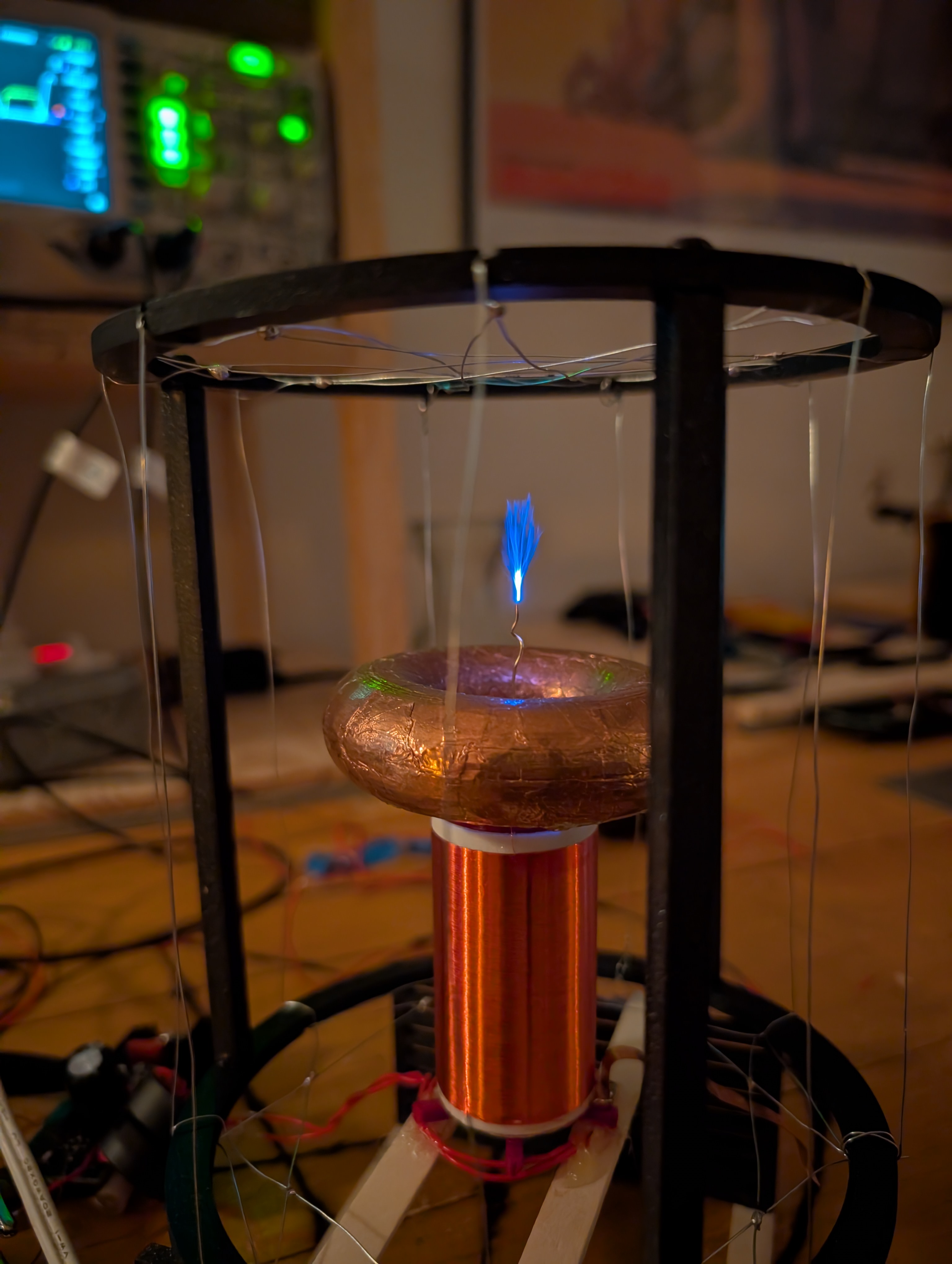
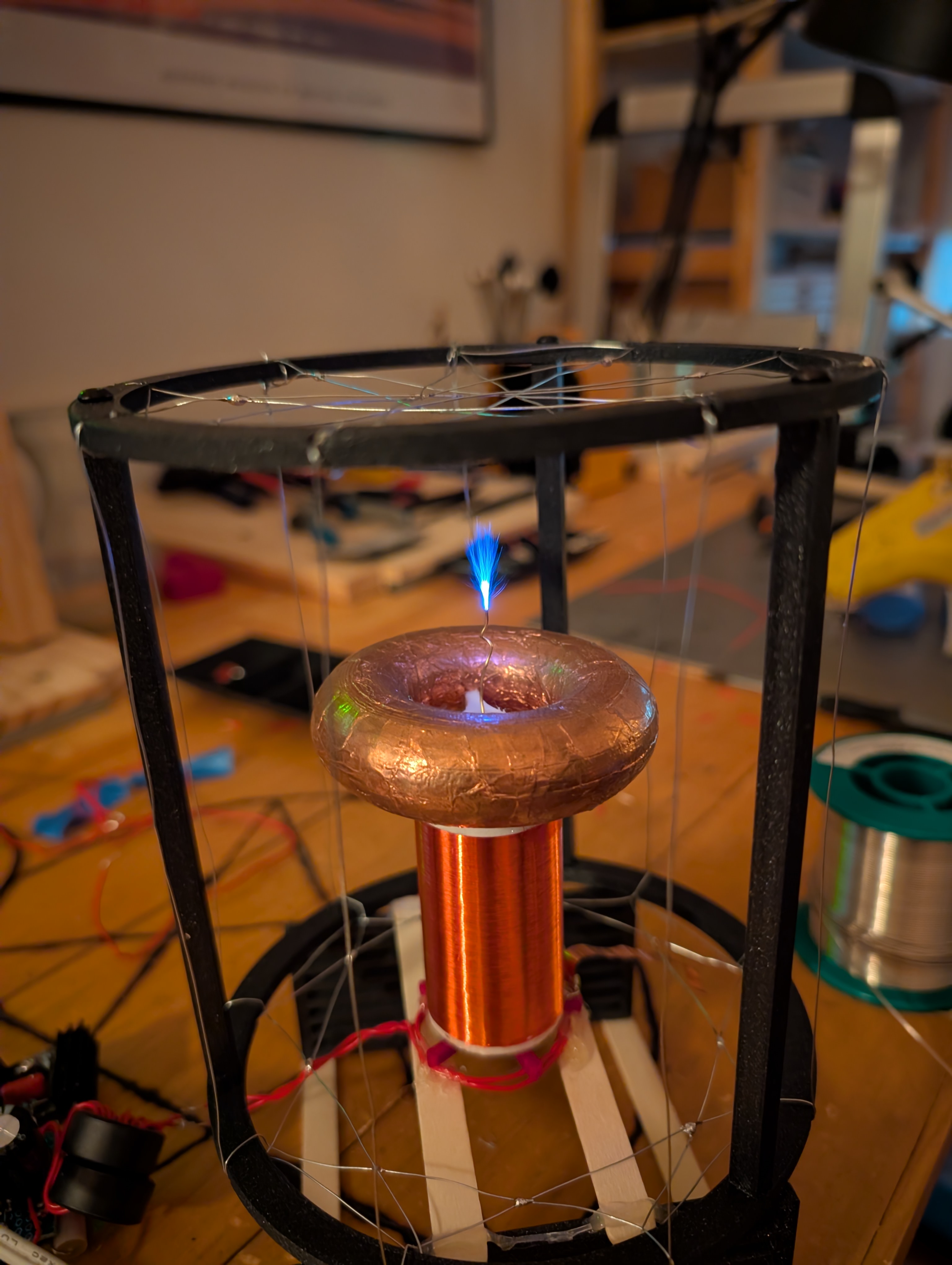
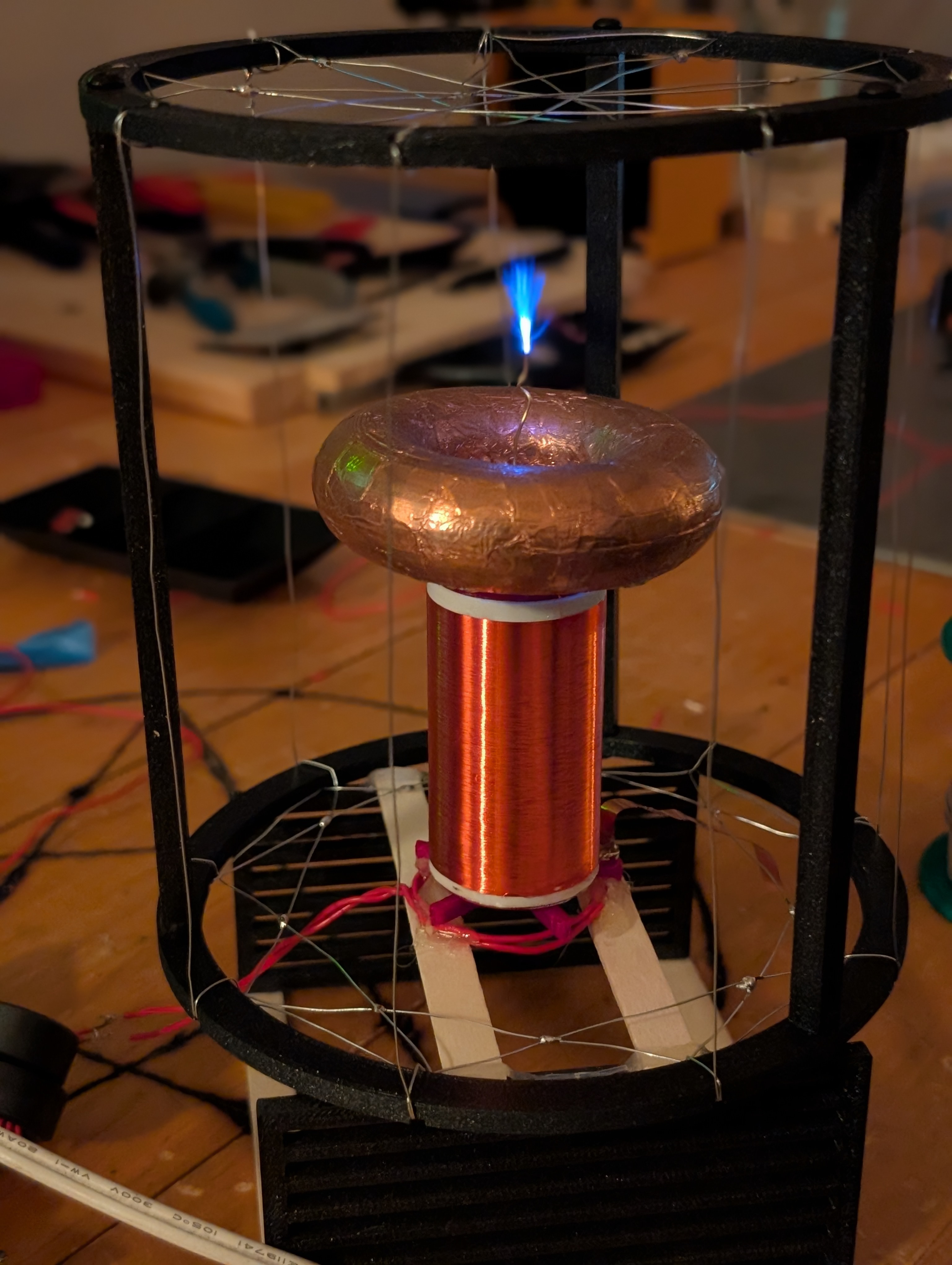
here's the lil' boy himself, operating at around 12 V at 2 A:

a small sstc in a faraday cage
for scale, that corona display is between 2 and 4 cm long, depending how you measure.

i'll try to actually write words for this post as opposed to just referring you to richie burnett's page on his hfsstc or steve ward's notes on his because (as gf will attest) i'm raring to go for the next one. 30 W simply is not enough power, at least how i built this thing.

i suppose i should explain why. see below…

notes on class e

the so-called "class e" amplifier is a single-switch rf amplifier topology that achieves high efficiency (north of 90%) via a carefully tuned resonant load. there is a great article by nathan o. sokal that goes into the theory and practice of class e amps in detail, better than i could; i'll just give the basics here, as well as my practical notes on using one of these in a tesla coil.

for standard class e, the circuit looks like this:

a class E amp schematic
an example class e amplifier, tuned roughly (!)

L6 is an rf choke, and its value is not critical provided it's sufficiently large. C8, C9, L7, and R7 form a tuned load network. when Q4 switches on, current increases through L6, storing energy. when Q4 switches off, that current shunts into C8, charging it and causing Q4's drain voltage to rise. this puts voltage across L7, causing its current to ramp up. the current through L7 eventually becomes greater than the current through L6, causing Q4's drain voltage to peak (at a little over 3Vht) and then drop as current starts to net flow out of C8. R7 prevents L7 from completely running away with things, though, damping what would be uncontrolled oscillation enough for the voltage at Q4's drain to just kiss zero when it turns on again.

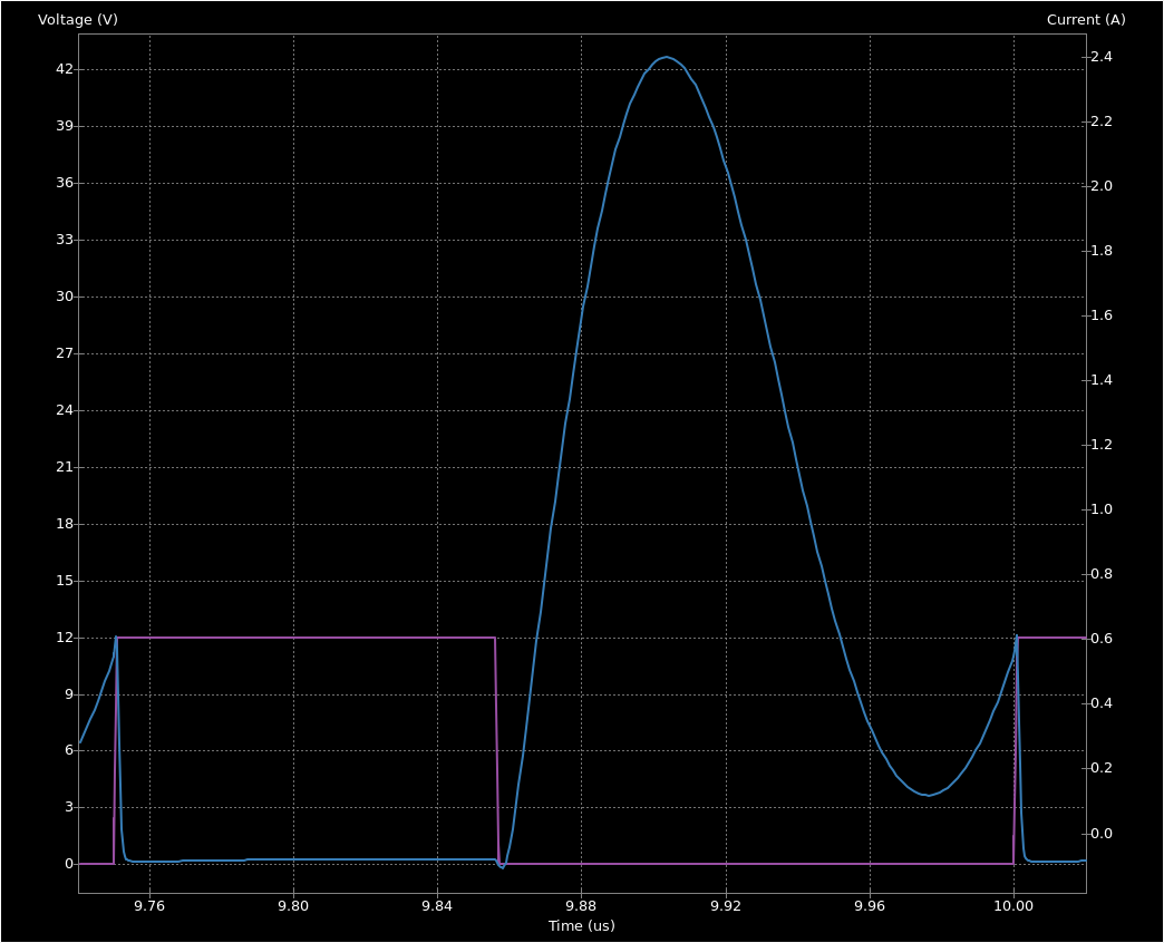
when this circuit is driven at 4 MHz, you get the characteristic class e waveform (gate drive in violet, C8's voltage / Q4's drain voltage in cyan):

a tuned waveform, drain voltage just kisses zero
the drain waveform of Q4 when the amp is in tune.

the reason for this circuit's efficiency is it avoids flowing current through Q4 while there's any meaningful voltage across it. most of the transistor current flows between 9.74 and 9.86 µs, and doesn't flow again until the voltage naturally drops back to zero. since power is proportional to both voltage and current, total dissipated energy in Q4 is \(\displaystyle E_{\text{dissipated}} = \int I(t)\ V(t)\ dt \) — the less accumulated current-voltage product you have, the less energy you'll lose in the switch. since \(I(t)\) and \(V(t)\) are nonzero at more or less disjoint times, Q4 dissipates very little total energy per cycle. in the biz, this is known as zvs (zero voltage switching), and is generally the reason anyone bothers with resonant switching at all. it is an interesting fact that switching loss (loss in the transition from on to off and vice versa) accounts for the bulk of energy loss in traditional (non-resonant) converters. advances in converter topology have drastically decreased that these days, though, along with more widespread use of GaN and SiC parts (which switch faster and thus accumulate less iv product)… and now i suspect i have yet another project on my hands.

if i deliberately detune the amp by decreasing L7 and C9, you get this: i'm not going to reproduce the classic class e tuning diagram here, partially because i'm not sure i could release under cc0 if i did that and partially to entice you to read some more fun pages in search of it.

an untuned waveform, drain voltage stays above zero
one of the out-of-tune drain waveforms you can get.

R7 is now sinking too much power per cycle relative to L7's energy storage, so the voltage no longer reaches zero, and the resonant frequency of L7 & C7 is too high, so Q4's drain voltage swings back up before it switches. if i were graphing power dissipated in Q4, you'd see a spike at 10 µs as its current ramps up at the same time as its voltage ramps down.

this is probably a good time to note that i've fibbed a bit: this sstc does not use a standard class e circuit. it uses something more similar to ward's hfsstc, in which you omit most of the load network and couple what would be the rf choke to the secondary, with the real rf choke placed elsewhere. i don't have a full schematic anywhere, but you can more or less reconstruct it from the linked project files at the end of the post. the drain waveform works out the same way, though, and the same efficiency considerations apply.

construction

…aaaaand that's about all the theory we have time for today, folks — let's get building!

secondary coil

i cannibalized an old coilform and toroid i made years ago, because they were some of the very first parts i ever 3d-printed and i wanted to put them to their original purpose. (some might say i started 3d-printing specifically so i could make nice toroids. some might say i have an obsession. i might agree with Some.)

a small tesla coil about twice as tall as a 9 V battery
(9 V battery for scale)

the coilform is extremely small as tesla coils go (which proved to be a problem later), but i wanted something that would easily fit on a desk. mostly just to see if i could pull it off; i built a traditional spark-gap coil back in high school that threw meter-long bolts, and from that i learned that physically larger coils are easier to get good results from.

the secondary coil end-on
another view of the coilform, showing the hole through the center, beveled edges to interface with the winding drive cones, and notches for the toroid support.

i originally wanted to wind this coil in #42 wire (totaling about 800 turns), since that's the smallest gauge i had on hand, but it turned out to be a real pain in the ass: i couldn't see where it was most of the time (it's much thinner than my hair), and it would cross itself while winding with the slightest provocation. after a few failed attempts, i decided to give up and use #38, which i've used for many years to great effect.

one thing i discovered: do not use double-sided tape or other adhesive on the start of a winding with wire like this! the wire wants a little bit of lateral play so that it can re-align itself as further turns are laid down by the machine (or by you, if you're insane enough to guide the wire by hand — it can be done…). i had a few false starts at #38 before i figured this out, but once i did, i secured the wire with blue painter's tape instead and things went beautifully.

a thin strip of wire on the right of the secondary
the start of the secondary winding. this photo was taken while the machine was running, hence the blur.
a fully-wound secondary
the secondary winding after the machine finished.

after winding, i carefully secured the ends of the wire to the coilform with cyanoacrylate and dipped the coil in a thick cut of shellac in ethanol i like ethanol as a solvent for this sort of thing, as i find it smells better than isopropanol and the whole solution is technically edible. shellac is used in, among other things, candy. to secure the turns in place, after which i let the coil air-dry thoroughly.

the secondary coil hanging inside a jar of shellac
i swung the arm of this indicator holder periodically down and up to dip the coil in a convenient manner.
the coil hanging over the shellac pot to drip off any excess
the coil after several shellac dips.

after drying the coil, i remounted the toroid, along with a screw in the center to (hopefully) serve as a breakout point. spoiler: this didn't work and i wound up using a cut piece of brass wire instead, as it was much sharper.

a tesla coil secondary with toroid and screw
the coil after re-mounting the toroid.

on the other end, for robustness, i terminated the hair-thin #38 wire in a brass rung, heat-sunk into the end of the coilform with a soldering iron.

a rectangular bit of brass wire embedded in the base of the secondary coilform
the small solder blob on the right side of the rung was the wire attachment point. the point of this rung was to (a) protect the fine wire and (b) provide an easy solder anchor for later connections.

primary

this isn't much of a section, because at any given time the primary coil was a few winds of hookup wire positioned carefully underneath the coil, without much structure to it. it turned out that proper primary inductance and primary-secondary coupling was critical to good operation of this coil, so i was always fiddling with it. i'll fix that property the next time i try a class e sstc (because of course there will be a next time, who do you think i am!?).

driver

i built the driver around an irf510 fet (known for being cheap and having reasonably good hf performance) and a ucc37322 low-side gate driver (known for me having one on hand). as best i could, i followed the layout guidelines in the UCC37322's datasheet regarding bypass capacitors and low-inductance layout, but there's only so much you can do, you know.

a perfboard with a FET and PDIP-8 soldered to it
the very beginning of the driver. ucc37322 to the left, irf510 to the right.

i built the driver to take an external gate signal input, which i fed for most of this project from my function generator. this allowed extremely easy retuning while the coil was in progress, as well as easy experimentation with interrupter ratios, and i will certainly be doing this again! previously i've built the core oscillator from the get-go, but i now think that's a mistake. running a class e coil with an interrupter at all may also be a mistake if you're not playing music… but see later on this page. ;)

i had most of the parts for the driver on hand, but special-ordered some metalized polypropylene capacitors for the resonant load after blowing up one of my salvage caps. these are the capacitors of choice for tesla coils for a few reasons: pp has relatively low loss at the frequencies we're talking about, they're film caps and as such have low esr and high linearity, and metalized film is "self-healing:" if an arc breaks out inside the capacitor, the sudden discharge current will cause that arc to vaporize metal film near the site of the punch-through, marginally reducing the capacitance but giving enough insulation around the hole that the capacitor will continue to function. (or so i'm told.)

a tesla coil and a driver on the bench
the first driver set up for testing (scope probe measuring resonance is out of frame).

i also custom-wound the rf choke (the two wire-wrapped toroids in the above & below photos). magnetics you should really just make yourself for one-off projects like this, and i have a small supply of ferrite in various sizes and shapes for doing just this. basically the only properties i thought about for the choke were

  1. the inductance (sufficiently high), and
  2. the current rating.

this is a dc choke, so the current rating is given by the lesser of the wire capacity and the saturation flux density of the core — in my case, most likely the latter. by the definition of inductance, for my estimated 500 mA load,

\begin{align*} \Phi & = LI \\ \implies B & = \frac{\Phi}{\text{area}} = \frac{LI}{\text{area}} \\[0.5em] & = \frac{ 47\ \text{µH} \cdot 500\ \text{mA} }{ 10\ \text{mm} \cdot 4.3\ \text{mm} \cdot 2 } \\[0.5em] & \approx 270\ \text{mT}, \end{align*}

which is pretty safe for a generic ferrite i got these in a lot on eBay with no knowledge of what material they were. the reason i have these cores on hand is for winding gate drive transformers, which i didn't have cause to use here. gdts are real cool things which i'll definitely discuss another time, but i had no use for them here because i only have one power transistor. lol. at low frequency. powdered iron or electrical steel could go higher (≥2 T for modern stuff), but i don't have that on hand, so. it worked as a choke, more or less, but certainly didn't block the heavy 100 Hz current oscillation with the interrupter on, so i did a second driver revision with some large filter capacitors and a larger heatsink on the main transistor.

an improved circuit board from above
the second driver revision.

this is the revision the coil shipped with. once i had the thing tuned properly and in (roughly) its final configuration, i whipped together a 1.47 MHz lc oscillator to hook to it instead of the function generator.

a photo of an oscillator circuit on perfboard.
the core oscillator. the potentiometer is a duty cycle adjustment, not a frequency adjustment, as i didn't have any trimcaps on hand.

i attached this oscillator after retuning the coil for cw operation, right before the end of the project.

faraday cage

both to prevent interference and provide a predictable topload capacitance (and also a little bit because i didn't feel like running an rf ground line) i stuck this lil' guy in a faraday cage. i initially made one using a metal screen, which was pretty easy and worked well (electrically), but obscured the coil more than i wanted it to.

a tesla coil inside a mesh cage
the coil swaddled in metal.

since part of the goal of a tesla coil is, necesarily, aesthetics, i made a new cage out of steel wire by hand. eventually i'll write a post on these (and do more formal testing than "does an antenna attached to my scope pick anything up outside the cage versus inside it?"), but for now have a photo.

a tesla coil inside a thin wire cage.
the coil merely cradled in metal.

tuning

to quote uzzors2k:

Despite having tuned my coil, I still don't have a good procedure for this. When you tune or adjust one component, everything else that was previously optimized needs readjusting.

granted, he ran his coil at 4.096 MHz while this one's running at 1.47 MHz, so i had a slightly easier time with readjustments — but the sentiment still holds. i don't really know how to tune this thing, and i wouldn't recommend this topology in the future, so take all this with a grain of salt.

secondary

first of all, i had to determine the resonant frequency of the secondary. i did this by either

  1. (outside the faraday cage) sticking a scope probe nearby and grounding the base of the secondary with the scope, or
  2. (inside the faraday cage) sticking an antenna (just a length of hookup wire) through, grounding the base of the secondary to the cage and the cage to the scope, with the probe measuring the signal on the antenna,

then sweeping the primary with a function generator and looking for a peak. this worked pretty well, as far as i can tell, giving me relatively consistent results for any given setup and correlating well with the observed ideal frequency to drive the coil at for the biggest sparks. the astute reader will notice the steel sheet underneath the coil and wonder whether it detuned things at all. having tested this setup both on the sheet and on the bare wood desk beneath: it does not appear to have.

a tesla coil with a scope probe suspended nearby
my open-air tuning setup, fres ≈ 1.6 MHz; eventually i moved this guy inside the cage and the frequency dropped to 1.47 MHz.

i did take off the toroid at one point, due to reports that a large top load isn't really beneficial for high-frequency coils like this one, but that increased fres to something like 10.2 MHz, which was too high for my tastes. so i kept it on.

primary

the main thing to know about primary tuning for these coils is that coupling is critical. class e coils benefit from relatively close coupling: the resonant tank is not left to ring as it is in a drsstc, so you really do want to transfer as much energy from primary to secondary on each cycle as possible, which equates to high mutual inductance. but if you have high mutual inductance, you also have high sensivity to the exact configuration of the primary, secondary, driver, housecat, phase of the moon, etc., because a slight disturbance will change the coupling.

i would recommend scrapping the separate-primary idea entirely and treating the secondary as the series lcr circuit that constitutes the usual class e load, driven from the 0 V end. i haven't tried this, but will be for the next class e coil i build.

driver

once i knew fres, i had to tune the driver. mostly this involved scoping the gate and drain waveforms at low voltage and adding/removing turns from the primary until the waveform was correct for class e (or close enough — hitting zero \(dV/dt\), the "just-kiss-zero" condition, is hard, but you can pretty reliably hit zero voltage on turn-on). i got pretty close, though:

an oscilloscope trace showing oscillation, big whoop
a 10-cycle burst, primary in tune. function generator in yellow, gate drive in cyan, drain voltage in magenta, secondary voltage (from antenna) in blue.

extending the pulse length allowed some actual resonant rise on the secondary:

an oscilloscope trace showing an increasing secondary voltage
a shot of the secondary coil building up voltage over a hundred or so cycles.

that drain voltage spike at the end, i suspect, is partially the current in the choke dropping and partially the secondary backfeeding the primary. it's only a problem if you're running the coil in interrupted mode, but if you are running the coil in interrupted mode you should really think about that! it was the limiting factor to input voltage for me, given that irf510s are only rated for 100 V.

one issue i ran into when switching to a larger form factor capacitor was ringing on the drain:

an oscilloscope trace showing severe spikes and ringing
ringing on the drain due to parasitic inductance in series with the resonant capacitor.

through simulation and some careful guesswork, i traced this to about 100 nH of parasitic inductance in series with the capacitor, due to the length of the fet pins between it and the cap. this is not the sort of thing you can remove — it's necessitated by the geometry of the circuit, so if you add a ferrite bead, an extra capacitor, etc., it only gets worse.

but if you think about it… that ringing is due to a tuned lc circuit, which requires some harmonic of the input signal to be nearby enough and sufficiently large to cause ringing… and the only place that can come from is the effective square wave at the drain itself. so i added a 10 Ω series resistor to the gate of the fet to slow down its switching times, and…

an oscilloscope trace showing much-improved spikes and ringing
after adding a gate resistor, the ringing improved enormously! this shot doesn't really do it justice: the ringing does not increase in proportion with increasing input voltage, so this looks worse than it was.

…there went the issue. there are reasons gate resistors exist. (this is not the only reason, but it was a surprising enough one that i thought it merited some exposition here.)

results

after figuring out the right resonant frequency and fiddling with the primary sufficiently, i increased the burst length to about 100 cycles and… sparks!

a very small corona discharge from the top of a tesla coil
first light!

i managed to get reasonably good output with 20 to 30 W of power draw (long-term average).

a more substantial tesla coil discharge
nth light, with the second driver revision and the interrupter on.

this was about the best i could manage within the hundred volt rating of the irf510 due to the resonant rise in the tank. i ran into heating issues in the driver initially, but after a lot of tuning i managed to get that down to the point where i could run the coil continuously, without an interrupter, without the driver overheating…

…except that the secondary coil itself started overheating at that point. #38 wire is quite thin, and the secondary had a measured resistance of about 95 Ω, which accounted for — i suspect, based on the simulated power dissipation of the parts and the drain waveform behavior when breakout occurred — half to most of the power loss of the coil.

it stayed cool enough for short runs, though, so of course when our friend chris came over we decided to plug him into it (via the function generator and an absolutely cursed bass-to-ttl adapter i whipped together):

in chris' words,

"i love him. i love our little demon."
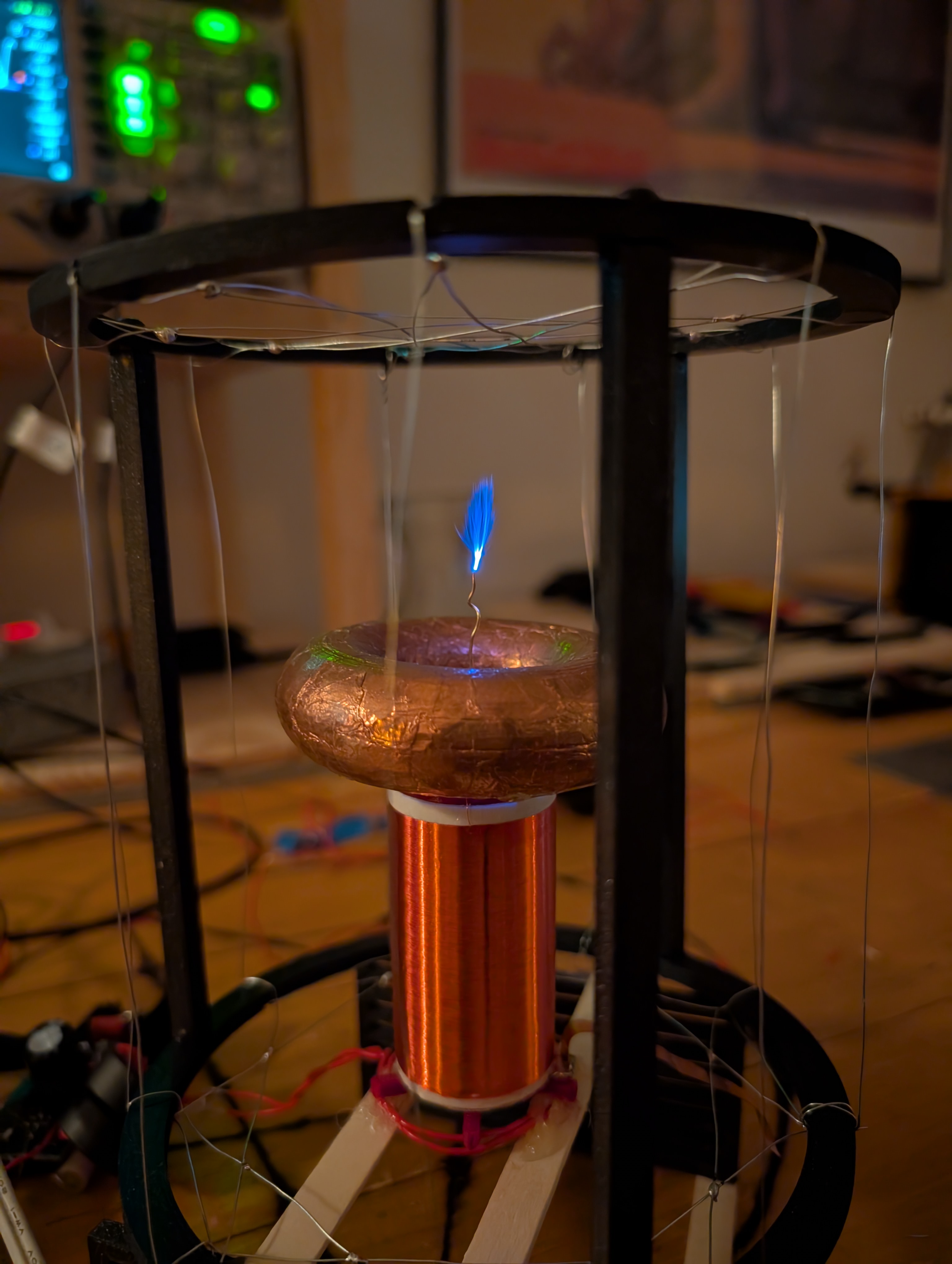
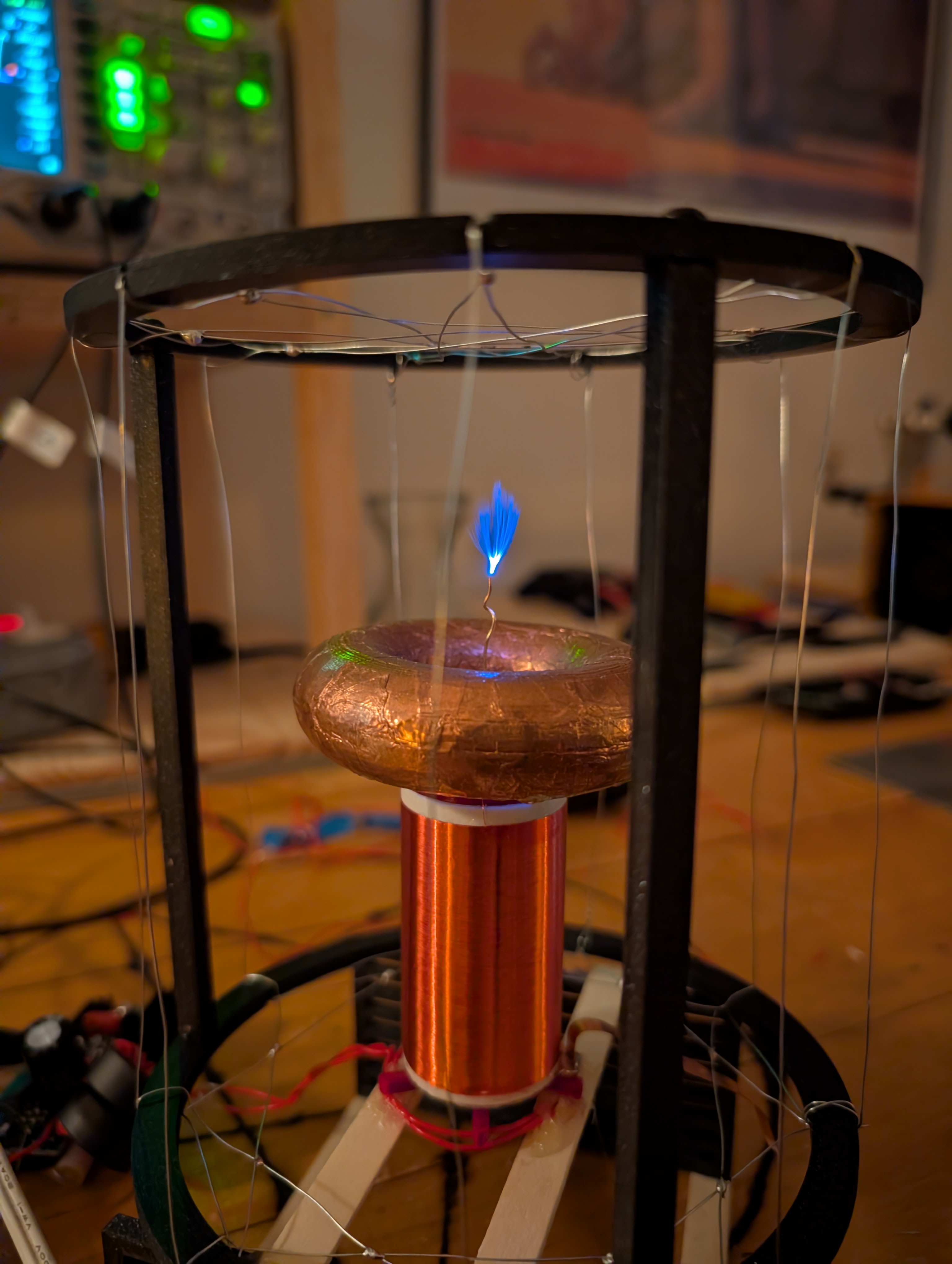
obligatory montage

here's a bunch of shots of the coil running on 12 V:

1.jpg
2.jpg
3.jpg
4.jpg
5.jpg
6.jpg

parting thoughts

a tesla coil sitting in the center of a pentagram
the finished coil.

this went pretty well.

for a low-power coil (comparatively speaking) that i spent about two weeks on, i'm satisfied, but also want more. because of course i do. the next coil will target at least a few hundred watts, perhaps even a kilowatt… and will be laaaaaaaaarger. i also think i can do better in this power bracket with more careful design, given the observed limitations of the secondary.

if when i build a coil like this again, i would:

  1. use thicker wire for the secondary and make it larger. this would shift dissipation to the plasma plume, improving efficiency; a key measure for tesla coils.
  2. drive the secondary directly, rather than through a coupled primary, so that precision coupling is no longer an issue; and
  3. push 300 W into it.

if you want the project files and my unfiltered notes, they're available here. my next coil will be a small drsstc, so stay tuned for that!

i'm looking for work! i have a formal background in electrical engineering with professional experience in software, firmware, & fabrication — and enjoy all of it. if you have work that spans software to hardware, full-time or freelance, email me at work@khz.ac.